Audio and Embedded Linux
Brief
Last time I used wrote kernel drivers for the ASoC (ALSA System on Chip) subsystem, the functionality was split up into these parts:
- Platform class driver that defines the SoC audio interface for the actual CPU itself. This includes both the DAI (Digital Audio Interface) and any potential audio muxes (e.g. i.MX6 has its AUDMUX).
- CODEC class driver that controls the actual CODEC.
- Machine drivers that is the magic glue between the SoC and the CODEC which connect the both interfaces. Such driver had to be written for each SoC-CODEC combination, and that does not scale very well.
Nowadays, most of the CODEC class drivers is now adapted to be described with the simple-audio-card [1] in a device tree, which will completely replace the machine drivers.
The goal with this post is to describe my work to setup a a 20W mono class-D audio amplifier to work with a i.MX8MM board.
General
The configuration of the CODEC is usually done on a I2C bus, even if other simple busses like SPI could be used as well. When configuration is sent over this simple bus, the audio data is sent over a complete different bus.
Audio data could be transferred in many different formats such as AC97, PCM or I2S.
To abstract this bus and handle it in a common way, we will just call it DAI, for Digital Audio Interface.
Different SoCs have of course different names on this as well. For example, Texas Instruments has its McASP, NXP uses SSI, Atmel SSC and so on.. We call it DAI all over.
Serial audio formats
AC97
AC97 is a commonly found interface on many PC cards, it's not that popular in embedded devices though. It's a five wire interface with:
- A reset line
- DATA_OUT for playback
- SDATA_IN for capture
- BCLK as bit clock, which is always driven by the CODEC
See the specification [4] for further reading.
I2S
I2S is a common 5 wire DAI often used in embedded systems. The TX (SDOUT) and Rx (SDIN) lines are used for audio transmission while the bit and frame clock are used for synchronization.
The signals are:
- Master clock or system clock, often referred to as MCLK, is the clock which the other clocks is derived from. This also clock the CODEC.
- Bit clock, often referred to as BCK or BCLK, varies depending on the sample rate.
- Frame clock, often referred to ass LRCLK (Left-Right Clock), FCLK (Frame clock) or WCLK (Word clock).
- Audio out, SDOUT
- Audio In, SDIN
The relationship between BCLK and LRCLK is
bclk = (sample rate) * Nchannels * (bit depth)
Some CODECs are able to use BCLK as their only clock, which leaving MCLK as optional. The CODEC we will use does supports this and is something we have to use due to HW constraints in number of available signals that should fit in a connector.
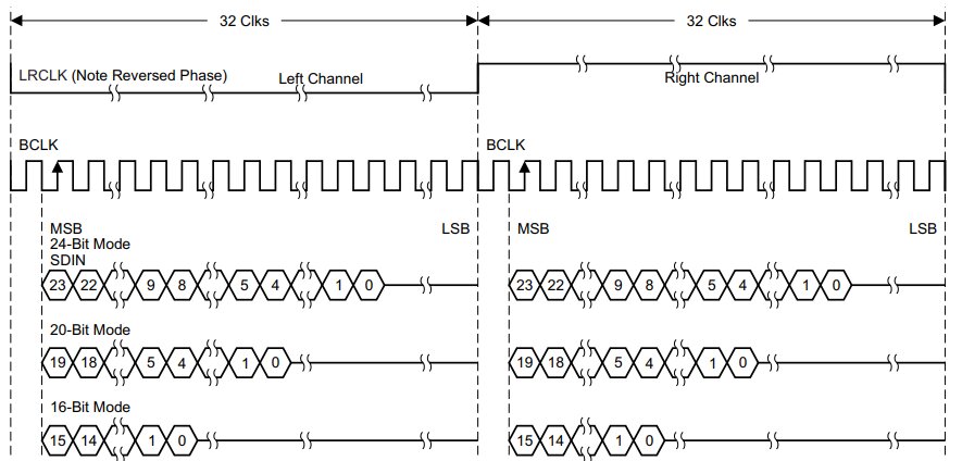
This is an illustration of the timing on the I2S bus with 64 BCLKs per LRCLK. Borrowed from the datasheet [5]:

I2S could be used with TDM format timing to support more audio channels on the same I2S bus. The timing will then look like this [5] :

PCM
PCM is a 4 wire interface that is quite similar to I2S. Same same but different.
Clocks
We have several clocks such as bit clock, frame clock and master clock. It's not written in stone which endpoint of the DAI that should generate these clocks, it's up to us to decide.
Either the SoC or CODEC generates some or all of the clocks, called clock master (e.g. bit clock master or frame clock master).
It's often easiest to let the CODEC generate all clocks, but some SoCs has specialized audio PLLs for this. In our case, the SoC will be clock master.
The Hardware
The SoC
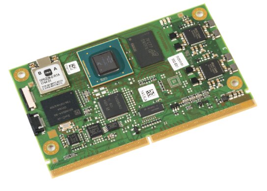
The board we are going to use is an evaluation board for a i.MX8MM module [2]. The CPU module supports two I2S busses and we are going to use one of them.

The CODEC
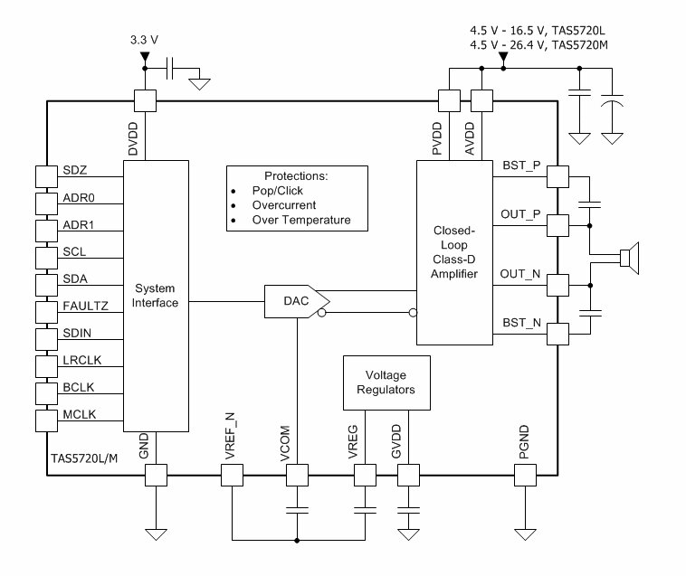
The CODEC we will use is is the TAS5720L [3] from Texas Instruments which has been supported in mainline since v4.6.

The TAS5720L device Serial Audio Interface (SAIF) supports a variety of audio formats including I2S, left-justified and Right justified. It also supports the time division multiplexed (TDM) format that is capable of transporting up to 8 channels of audio data on a single bus.
It uses I2C as configuration interface.
We will use I2S with TDM as DAI and I2C as configuration interface.
The Software
As we mostly got rid of the machine drivers and can describe the CODEC bindings using device tree, the setup is mostly a exercise in device tree writing rather than C.
The device tree node to setup the sound card is simple-audio-card [6].
SAI node
The Synchronous Audio Interface (SAI) module is the HW part of the i.MX8 SoC that are used to generate the digital audio.
We are going to use the SAI5 interface as it's routed from the sm2s-imx8mm module. The node is properly configured in an interface (.dtsi)-file, so we only have to enable it:
&sai5 {
    status = "okay";
};
CODEC node
The TAS5720L is connected to the I2C3 bus and respond to the slave address 0x6c. Besides the compatible and reg properties, the node also requires phandle for a 3V3 supply that supplies the digital circuitry and a phandle for the Class-D amp and analog part.
The hardware does not have such controllable supplies so we have to create fixed regulators for that:
/ {
    reg_audio_p: regulator-audio {
        compatible = "regulator-fixed";
        regulator-name = "audio power";
        pinctrl-names = "default";
        regulator-min-microvolt = <12000000>;
        regulator-max-microvolt = <12000000>;
    };

    reg_audio_d: regulator-audio {
        compatible = "regulator-fixed";
        regulator-name = "audio digital";
        pinctrl-names = "default";
        regulator-min-microvolt = <3300000>;
        regulator-max-microvolt = <3300000>;
    };
};
And the device node for the CODEC itself:
&i2c3 {
tas5720: tas5720@6c {
#sound-dai-cells = <0>;
reg = <0x6c>;
compatible = "ti,tas5720";
dvdd-supply = <®_audio_d>;
pvdd-supply = <®_audio_p>;
};
};
Sound node
Now it's time to setup the sound node!
First we have to specify which audio format we intend to use by setting simple-audio-card,format to i2s.
We also have to setup the two DAIs (CPU & CODEC) that we are going to use.
This is done by creating sub nodes and refer to the SAI module node and CODEC node as sound-dai respectively.
These sub nodes are referred to when assign frame-master and bitclock-master in the sound node. As we want the SoC to generate both frame- and bit-clock, set cpudai as clock master for both.
/ {
    sound-tas5720 {
        compatible = "simple-audio-card";
        simple-audio-card,name = "tas5720-audio";
        simple-audio-card,format = "i2s";
        simple-audio-card,frame-master = <&cpudai>;
        simple-audio-card,bitclock-master = <&cpudai>;

        cpudai: simple-audio-card,cpu {
            sound-dai = <&sai5>;
            clocks = <&clk IMX8MM_CLK_SAI5_ROOT>;

        };

        simple-audio-card,codec {
            sound-dai = <&tas5720>;
            clocks = <&clk IMX8MM_CLK_SAI5_ROOT>;
        };
    };
};
Sound test
Now we should have everything in place!
Lets use speaker-test, which is part of alsa-utils [8] to test our setup.
root@imx8board:~# speaker-test

speaker-test 1.2.5.1

Playback device is default
Stream parameters are 44000Hz, S16_LE, 1 channels
Using 16 octav es of pink noise
[   12.257438] fsl-sai 30050000.sai: failed to derive required Tx rate: 1411200
That did not turn out well.
Debug clock signals
Lets look what our clock tree looks like:
root@imx8board:~# cat /sys/kernel/debug/clk/clk_summary
    ...
    audio_pll2_ref_sel                0        0        0    24000000          0     0  50000
       audio_pll2                     0        0        0   361267200          0     0  50000
          audio_pll2_bypass           0        0        0   361267200          0     0  50000
             audio_pll2_out           0        0        0   361267200          0     0  50000
    audio_pll1_ref_sel                0        0        0    24000000          0     0  50000
       audio_pll1                     0        0        0   393216000          0     0  50000
          audio_pll1_bypass           0        0        0   393216000          0     0  50000
             audio_pll1_out           0        0        0   393216000          0     0  50000
                sai5                  0        0        0    24576000          0     0  50000
                   sai5_root_clk       0        0        0    24576000          0     0  50000
    ...
The sai5 clock is running at 24576000Hz, and indeed, it's hard to find a working clock divider to get 1411200Hz.
audio_pll2 @ 361267200 looks better. 361267200/1411200=256, allmost perfect!
Then we need to reparent the sai5 module, this is done in the device tree as well:
&sai5 {
    status = "okay";
    assigned-clock-parents = <&clk IMX8MM_AUDIO_PLL2_OUT>;
    assigned-clock-rates = <11289600>;
};
Here is our new clock tree:
root@imx8board:~# cat /sys/kernel/debug/clk/clk_summary
    ...
    audio_pll2_ref_sel                0        0        0    24000000          0     0  50000
       audio_pll2                     0        0        0   361267200          0     0  50000
          audio_pll2_bypass           0        0        0   361267200          0     0  50000
             audio_pll2_out           0        0        0   361267200          0     0  50000
                sai5                  0        0        0    11289600          0     0  50000
                   sai5_root_clk       0        0        0    11289600          0     0  50000
    ...
We can see that the frequency is right and also that we now derive our clock from audio_pll2_out instead of audio_pll1.
The speaker-test software is also happier:
root@imx8board:~# speaker-test

speaker-test 1.2.5.1

Playback device is default
Stream parameters are 44000Hz, S16_LE, 1 channels
Using 16 octaves of pink noise
Rate set to 44000Hz (requested 44000Hz)
Buffer size range from 3840 to 5760
Period size range from 1920 to 1920
Using max buffer size 5760
Periods = 4
was set period_size = 1920
was set buffer_size = 5760
 0 - Front Left
Great!
Use BCLK as MCLK
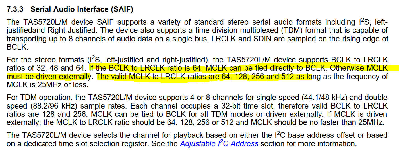
Due to my hardware constraints, I need to use the bit clock as master clock. If we look in the datasheet [5] :

If the BCLK to LRCLK ratio is 64, we could tie MCLK directly to our BCLK!
We already know our BCLK, it's 1411200Hz, and the frame clock (LRCLK) is the same as the sample rate (44kHz). We could verify that with the oscilloscope.
Bitclock:

Frameclock:

That is not a ratio of 64.
There is not much to do about the frame clock, it will stick to the sample rate. If we make use of TDM though, we can make the bit clock running faster with the same frame clock!
Lets add 2 TDM slots @ 32bit width:
/ {
    sound-tas5720 {
        compatible = "simple-audio-card";
        simple-audio-card,name = "tas5720-audio";
        simple-audio-card,format = "i2s";
        simple-audio-card,frame-master = <&cpudai>;
        simple-audio-card,bitclock-master = <&cpudai>;

        cpudai: simple-audio-card,cpu {
            sound-dai = <&sai5>;
            clocks = <&clk IMX8MM_CLK_SAI5_ROOT>;
            dai-tdm-slot-num = <2>;
            dai-tdm-slot-width = <32>;
        };

        simple-audio-card,codec {
            sound-dai = <&tas5720>;
            clocks = <&clk IMX8MM_CLK_SAI5_ROOT>;
        };
    };
};
Verify the bitclock:

Lets calculate: 2820000/44000 ~= 64! We have reached our goal!
Final device tree setup
This is what the final device tree looks like:
/ {
sound-tas5720 {
compatible = "simple-audio-card";
simple-audio-card,name = "tas5720-audio";
simple-audio-card,format = "i2s";
simple-audio-card,frame-master = <&cpudai>;
simple-audio-card,bitclock-master = <&cpudai>;
cpudai: simple-audio-card,cpu {
sound-dai = <&sai5>;
clocks = <&clk IMX8MM_CLK_SAI5_ROOT>;
dai-tdm-slot-num = <2>;
dai-tdm-slot-width = <32>;
};
simple-audio-card,codec {
sound-dai = <&tas5720>;
clocks = <&clk IMX8MM_CLK_SAI5_ROOT>;
};
};
reg_audio_p: regulator-audio {
compatible = "regulator-fixed";
regulator-name = "audio power";
pinctrl-names = "default";
regulator-min-microvolt = <12000000>;
regulator-max-microvolt = <12000000>;
};
reg_audio_d: regulator-audio {
compatible = "regulator-fixed";
regulator-name = "audio digital";
pinctrl-names = "default";
regulator-min-microvolt = <3300000>;
regulator-max-microvolt = <3300000>;
};
};
&i2c3 {
tas5720: tas5720@6c {
#sound-dai-cells = <0>;
reg = <0x6c>;
compatible = "ti,tas5720";
dvdd-supply = <®_audio_d>;
pvdd-supply = <®_audio_p>;
};
};
&sai5 {
status = "okay";
assigned-clock-parents = <&clk IMX8MM_AUDIO_PLL2_OUT>;
assigned-clock-rates = <11289600>;
};
Conclusion
simple-audio-card is a flexible way to describe the audio routing and I strongly prefer this way over write a machine driver for each SoC-CODEC setup.
My example here is kept to a minimum, you probably want to add widgets and routing as well.
simple-audio-card does support rather complex setup with multiple DAI links, amplifier and such. See the device tree bindings [6] for further reading.
References
| [1] | https://www.kernel.org/doc/Documentation/devicetree/bindings/sound/simple-card.txt |
| [2] | https://embedded.avnet.com/product/msc-sm2s-imx8m/ |
| [3] | https://www.ti.com/product/TAS5720L |
| [4] | http://www.intel.com/p/en_US/business/design |
| [5] | (1, 2, 3) https://www.ti.com/lit/ds/symlink/tas5720l.pdf |
| [6] | (1, 2) https://www.kernel.org/doc/Documentation/devicetree/bindings/sound/simple-card.yaml |
| [7] | https://www.kernel.org/doc/Documentation/devicetree/bindings/sound/tas5720.txt |
| [8] | https://github.com/alsa-project/alsa-utils |