Repair of an IC-211E HAM Radio
A friend of mine (SM7FWZ [3] ) gave me an ICOM IC-211E, a 2M all mode transceiver that I'm having a lot of fun with. When I got it, it had one drawback - transmitting on SSB (Single Side Band) didn't work very well, neither for USB (Upper Side Band) nor LSB (Lower Side Band).
The signal that reached the antenna was really disturbed, so here is something that needs to be fixed!
IC-211E
IC-211E [1] is a Amateur VHF (Very High Frequency) tranceiver for the 2m (144-146MHz) radio band.
It supports FM (Frequency Modulation), SSB (Single Side Band) and CW (Continuous Wave) mode and has a transmit power of 10W.
The model was manufactured in Japan 1976-1978, so the radio is at least 10 years older than me..
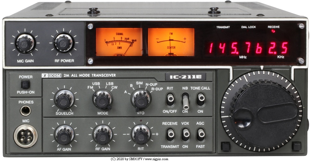
It is a pretty nice radio though. I've mostly used it to communicate via repeaters (FM, vertical polarized antenna), but I currently have it connected to a horizontal polarized Yagi antenna on the roof to try out SSB/CW more seriously. It is only a matter of time.
Problem description
What I knew was that:
- The signal is distrubed when transmitting on SSB
- FM works well
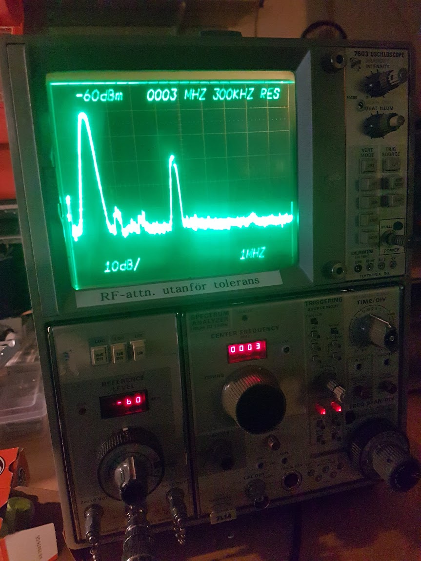
At least something is working - that is good. Let's connect it to a spectrum analyser to see how bad it is.
Outch.
This is when I do send a tone (single frequency). What to expect is a single peak, not this mess.
Troubleshooting
One thing I love with HAM radios is that they are built to be repaired. It is not that hard to find schematics, block diagrams or service manuals for a particular radio. Not like most of today's electronics.
The block diagram for the receiver & transmitter looks as follow:
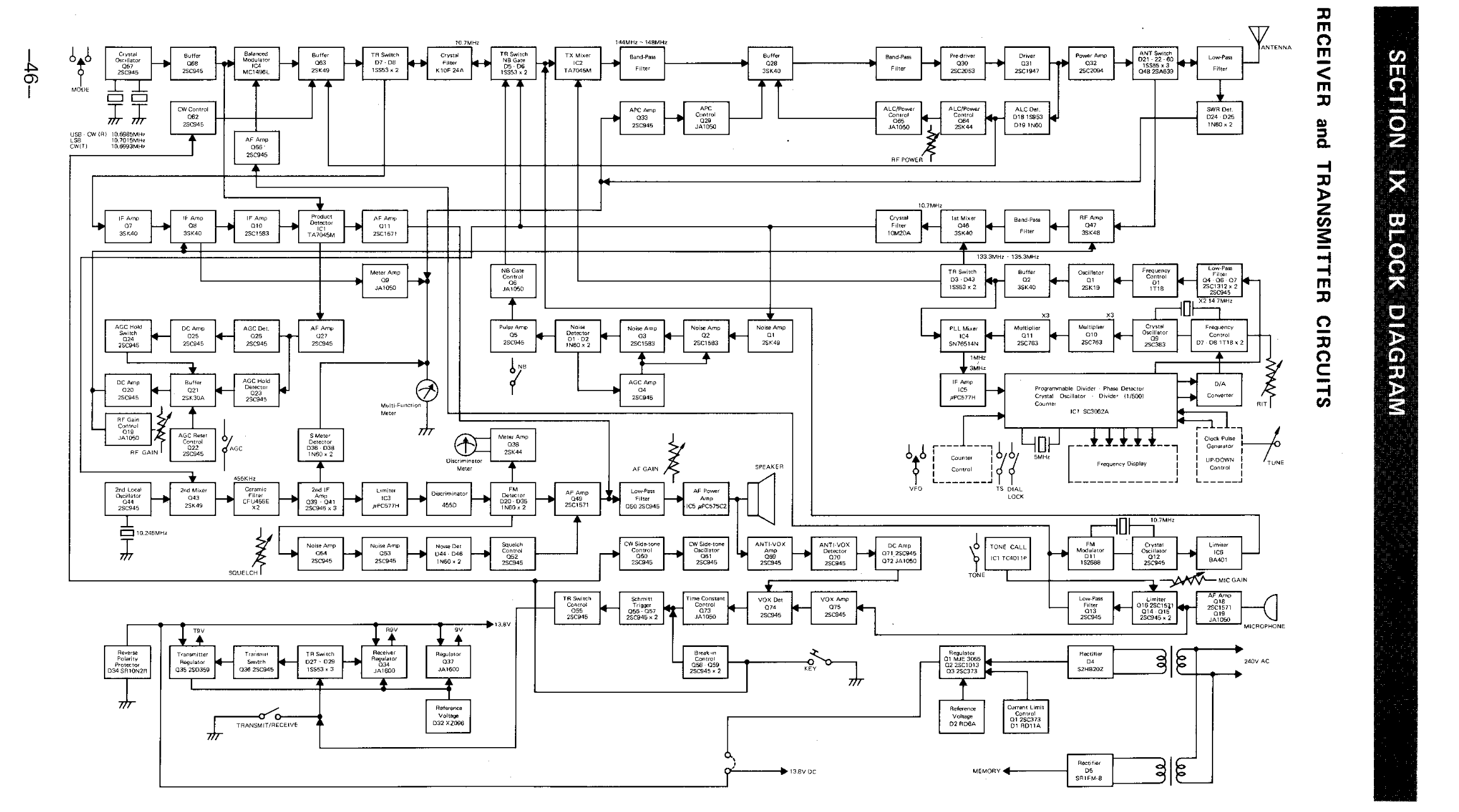
It looks complex. But the receiver part is the most complex one, the transmitter is actually quite straight forward.
If we look into the path when transmitting a tone on SSB, we can see that we will go through these blocks:
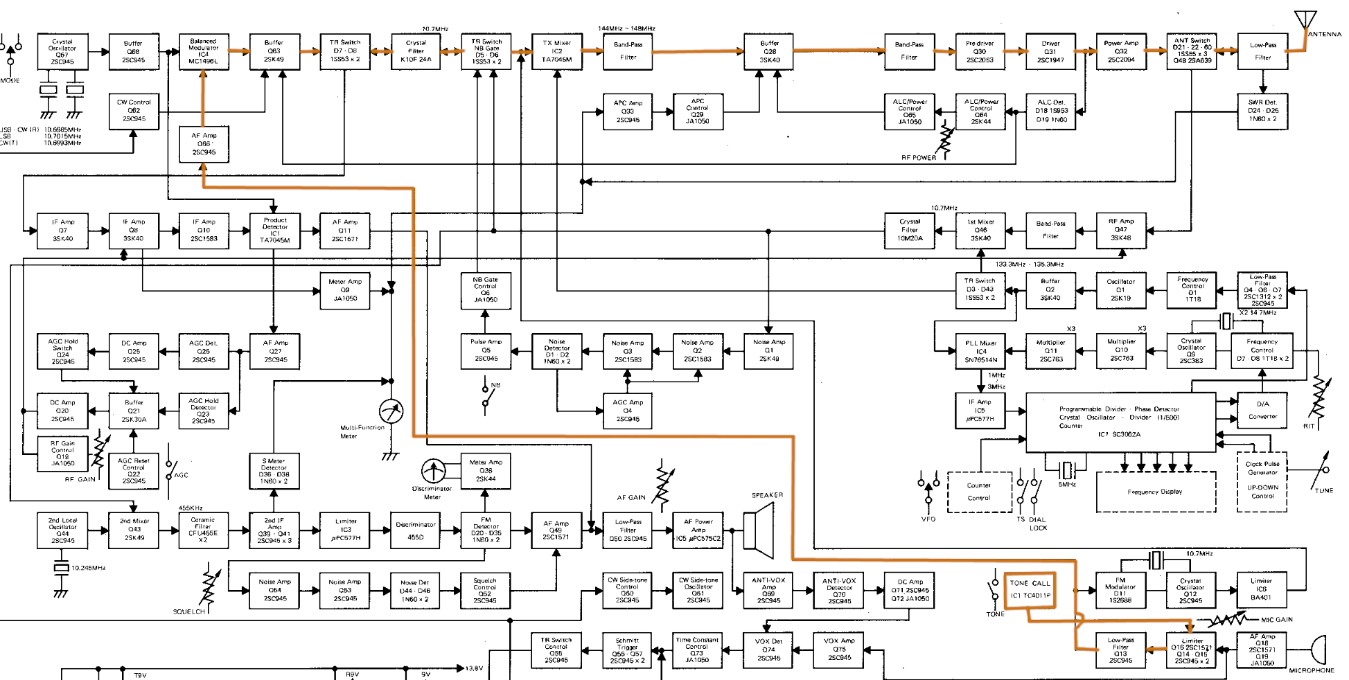
Ok, that is quite many blocks... but we did have more information; The FM path does actually works and most of blocks are common for SSB and FM.
Here is the transmit path when doing the same thing for FM:
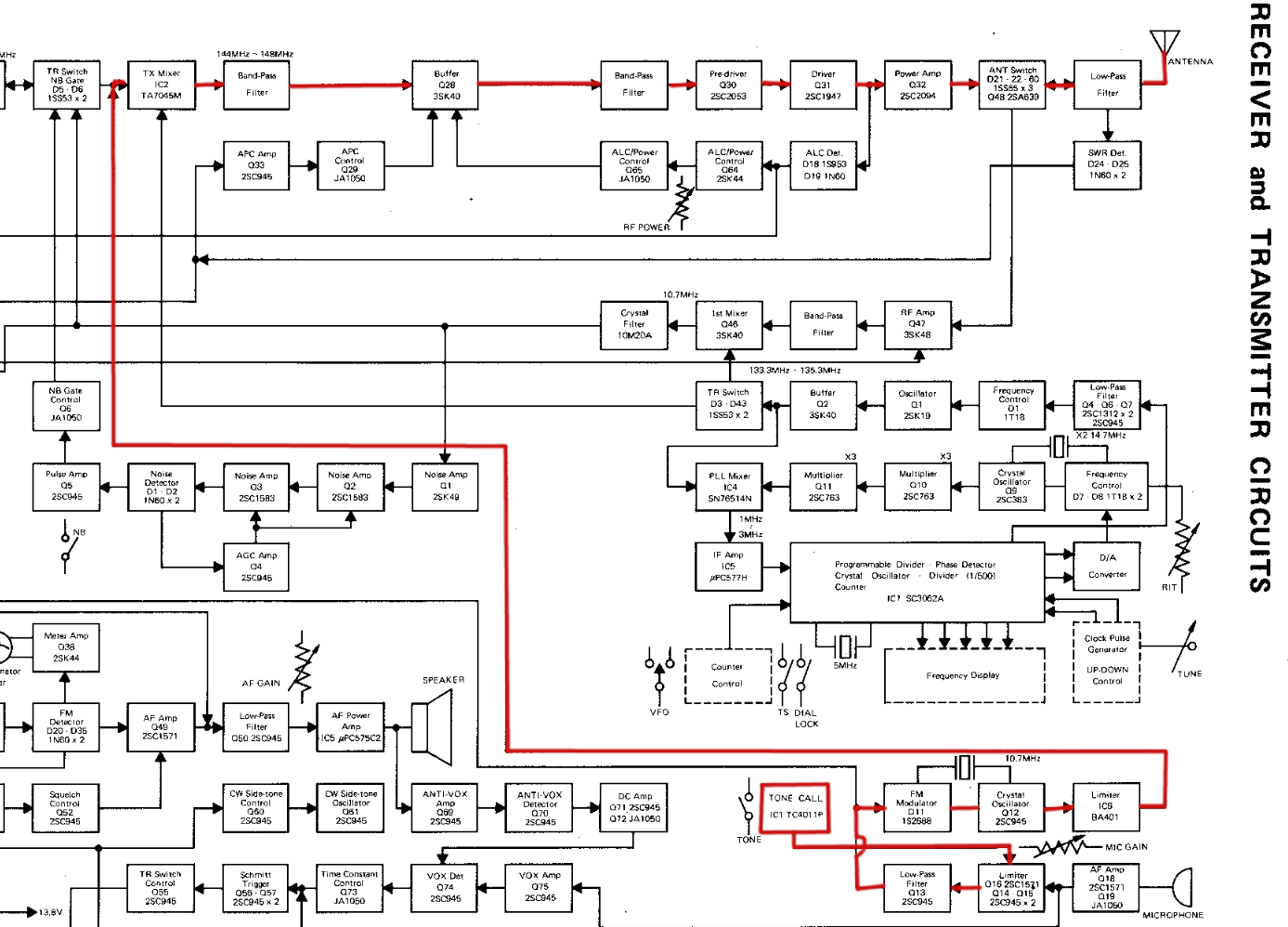
As there are so many common blocks between SSB and FM we can limit he troubleshooting to the following blocks:
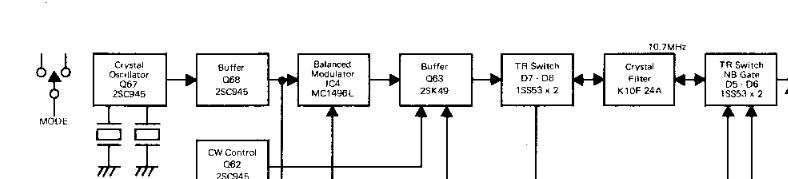
The crystal oscillator was verified with an oscilloscope and it worked as expected. The filters does not usually breaks and the buffer stages is just a set of transistors that was easy to verify. That directs my suspicious to the Balanced Modulator (MC1496).
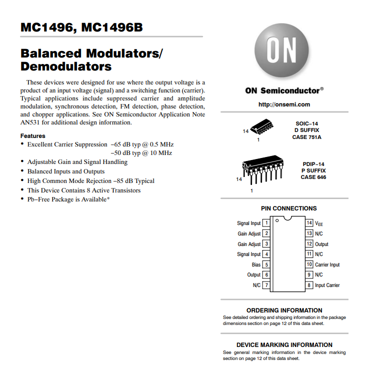
MC1496
MC1496 [2] is a balanced modulator/demodulator, and if something is wrong with that IC then it is not impossible that we get disturbed signals.
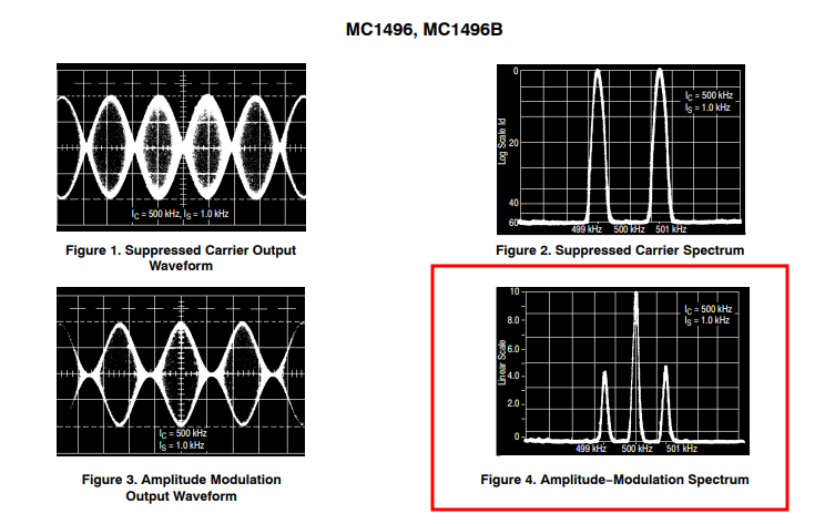
This is what the signal should look like on the spectrum analyzer when transmitting an AM (Amplitude Modulation) signal. But as we transmit SSB, we should only see one of the upper or lower peaks.
I bought a new chip from eBay to replace it with.
Replace the broken IC
As soon as the replacement IC has arrived, it was time to pick up the screwdriver.
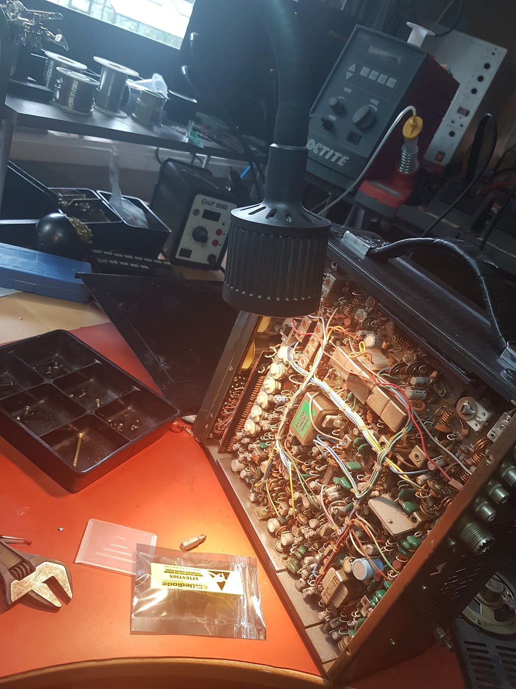
It is just so cool to know that these electonics is more than 10 years older than myself.
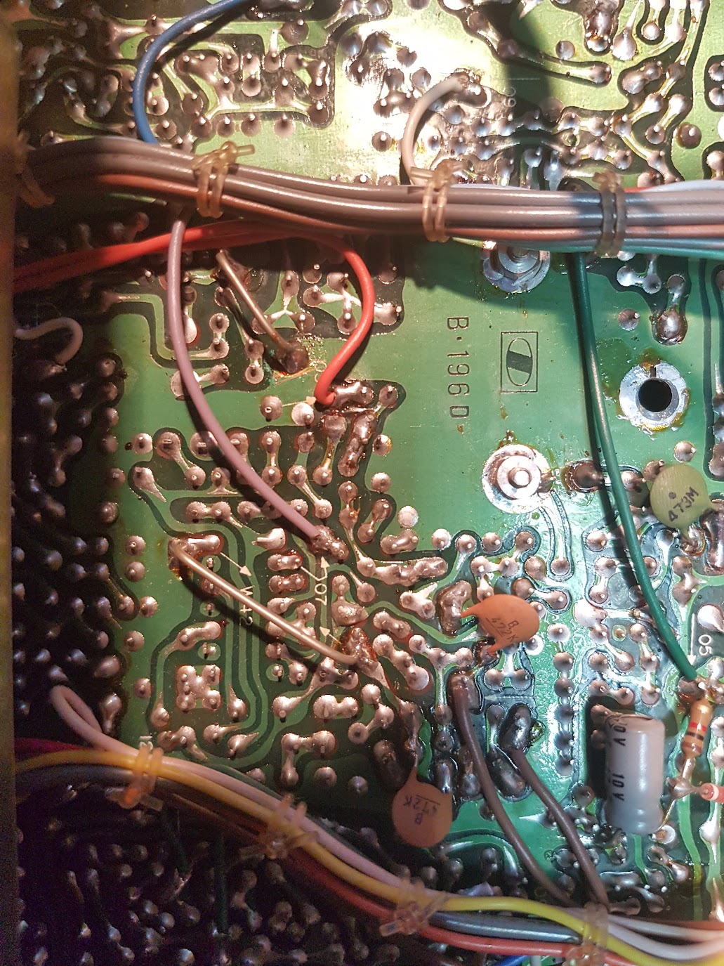
The service manual guides me to where I could find the IC:
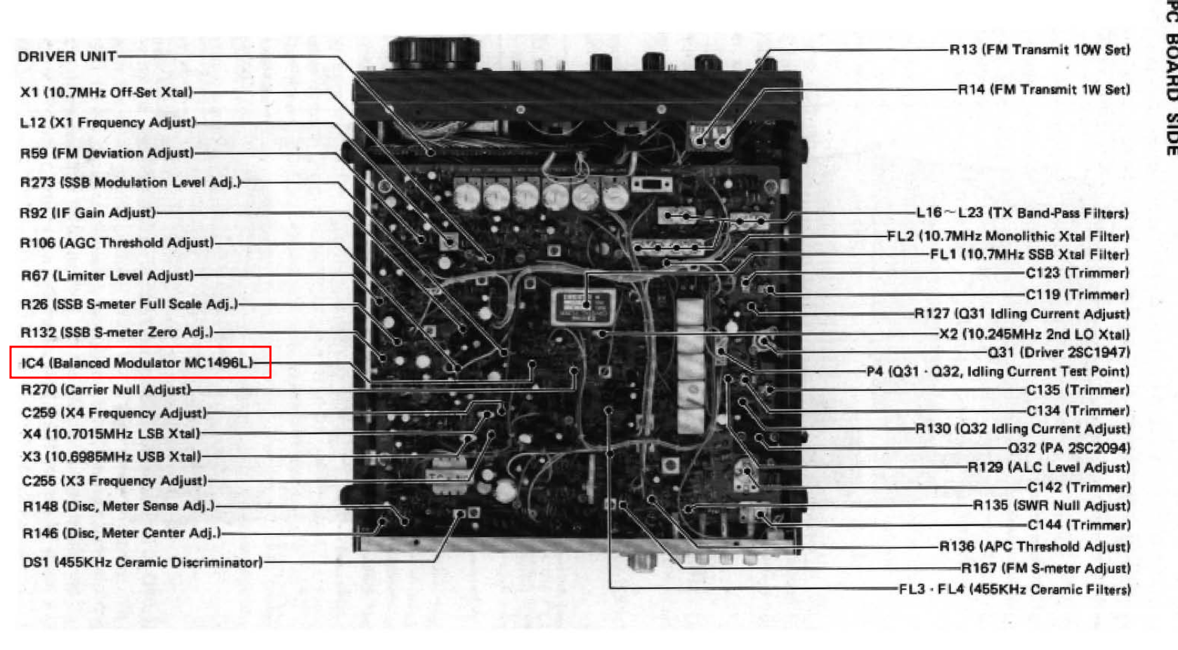
And there it is!
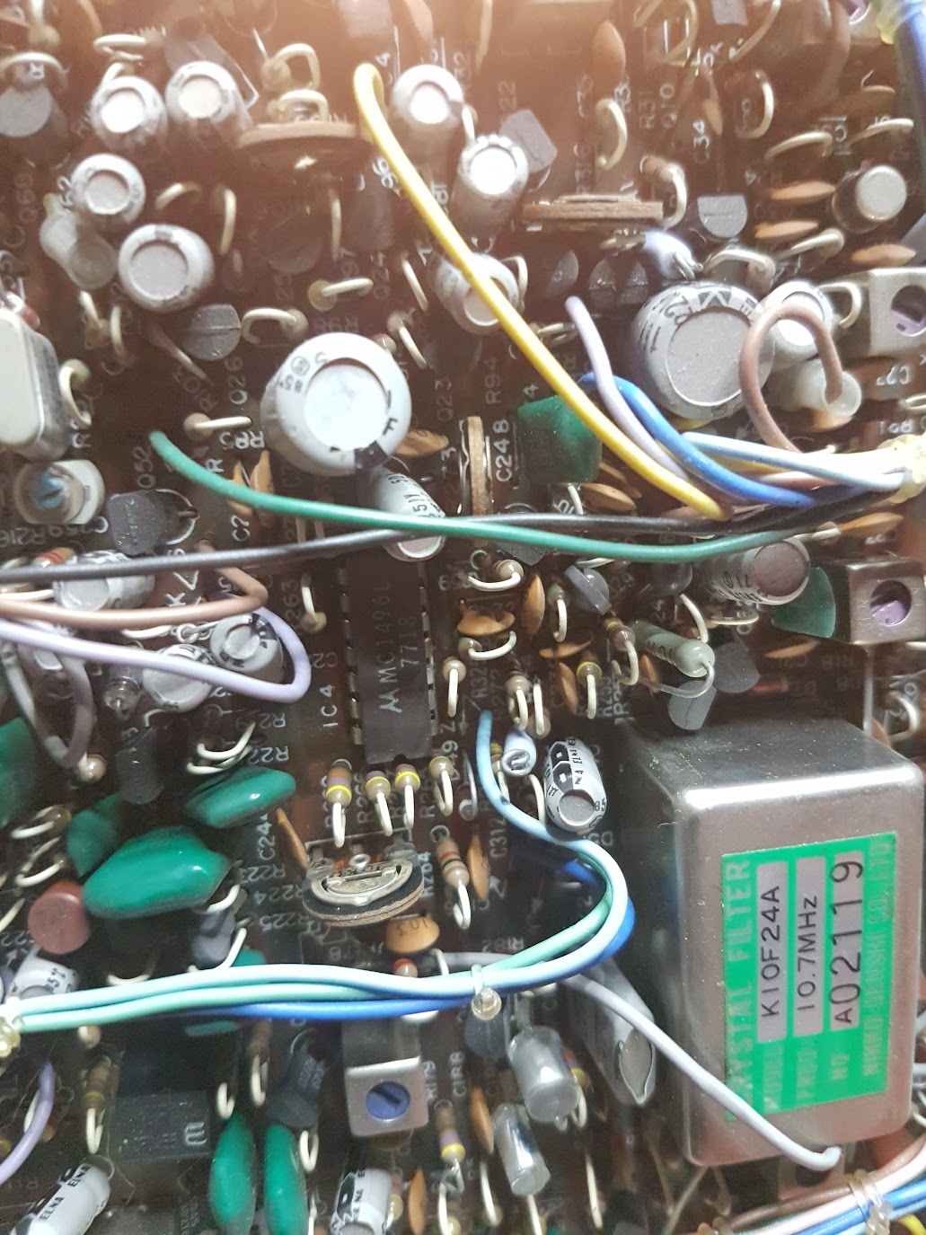
There are just so many connectors and stuff that needs to be removed in order to make it though with a soldering gun. I even had to temporary move jumper cables on the back.
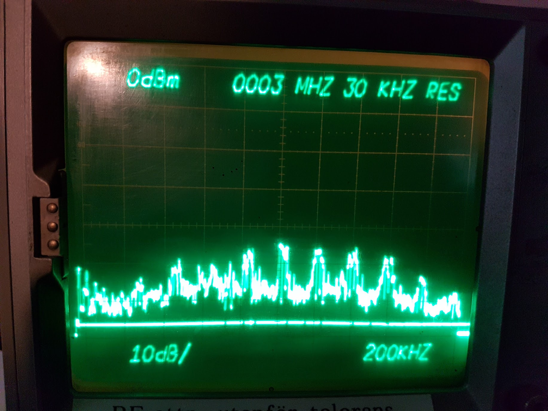
The result
After replacing the modulator IC the carrier finally looks like we would like it to - A single peak with no interference!