Overview
In the previous part we prepared Zephyr for our soon to be born driver.
Now we have finally come to the fun point - write the actual driver code!
Driver API
I used to write code for the Linux kernel which is a little bit more complex kernel than Zephyr. The Zephyr driver API for DAC must be one of the most simpliest API:s I have ever seen.
You have to populate just only two functions in the struct dac_driver_api found in inlcude/zephyr/drivers/dac.h:
 * DAC driver API
 *
 * This is the mandatory API any DAC driver needs to expose.
 */
__subsystem struct dac_driver_api {
    dac_api_channel_setup channel_setup;
    dac_api_write_value   write_value;
};
Where channel_setup is used to configure the channel:
/**
 * @brief Configure a DAC channel.
 *
 * It's required to call this function and configure each channel before it's
 * selected for a write request.
 *
 * @param dev          Pointer to the device structure for the driver instance.
 * @param channel_cfg  Channel configuration.
 *
 * @retval 0         On success.
 * @retval -EINVAL   If a parameter with an invalid value has been provided.
 * @retval -ENOTSUP  If the requested resolution is not supported.
 */
typedef int (*dac_api_channel_setup)(const struct device *dev,
             const struct dac_channel_cfg *channel_cfg);
dac_channel_cfg specifies the channel and desired resolution:
/**
 * @struct dac_channel_cfg
 * @brief Structure for specifying the configuration of a DAC channel.
 *
 * @param channel_id Channel identifier of the DAC that should be configured.
 * @param resolution Desired resolution of the DAC (depends on device
 *                   capabilities).
 */
struct dac_channel_cfg {
    uint8_t channel_id;
    uint8_t resolution;
};
Our DAC supports 8 channels and 8bit or 10bit resolution.
write_value is rather self-explained:
/**
 * @brief Write a single value to a DAC channel
 *
 * @param dev         Pointer to the device structure for the driver instance.
 * @param channel     Number of the channel to be used.
 * @param value       Data to be written to DAC output registers.
 *
 * @retval 0        On success.
 * @retval -EINVAL  If a parameter with an invalid value has been provided.
 */
typedef int (*dac_api_write_value)(const struct device *dev,
                                uint8_t channel, uint32_t value);
It writes value to channel on dev.
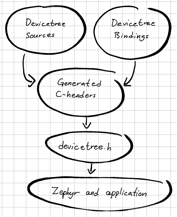
Device tree
We have to create a device node that represent the DAC in order to make it available in Kconfig.
During the build, we specified rpi_pico as board, remember?
west build -b rpi_pico ....
which uses the boards/arm/rpi_pico/rpi_pico.dts device tree. It's possible to add the DAC node directly to rpi_pico.dts, but it's strongly preferred to use overlays.
Device tree overlays
A Device tree overlay is a fragment of a device tree that extends or modifies the existing device tree. As we do not want to add the DAC to all rpi_pico boards, but only to those that actually have it connected, overlays is the way to go.
Device tree overlays can be specified in two ways:
- DTC_OVERLAY_FILE or
- .overlay files
The CMake variable DTC_OVERLAY_FILE contains a space- or semicolon-separated list of overlay files that will be used to overlay the device tree.
.overlay files on the other hand, is overlays that the build system automatically will pickup in the following order:
- If the file boards/<BOARD>.overlay exists, it will be used.
- If the current board has multiple revisions and boards/<BOARD>_<revision>.overlay exists, it will be used. This file will be used in addition to boards/<BOARD>.overlay if both exist.
- If one or more files have been found in the previous steps, the build system stops looking and just uses those files.
- Otherwise, if <BOARD>.overlay exists, it will be used, and the build system will stop looking for more files.
- Otherwise, if app.overlay exists, it will be used.
Our device tree overlay looks as follow:
 &spi0 {
    dac0: dac0@0 {
        compatible = "lltc,ltc1665";
        reg = <0>;
        spi-max-frequency = <1000000>;
        duplex = <0>;
        #io-channel-cells = <8>;
        status = "okay";
    };
};
- compatible is matching against our driver
- reg specify chip select 0
- spi-max-frequency is set to 1MHz
- duplex specifies duplex mode, 0 equals full duplex
- status is set to "okay"
The driver
The chip itself is quite simple and that is reflected in the driver.
Here is the complete driver code:
/*
* Driver for Linear Technology LTC1660/LTC1665 DAC
*
* Copyright (C) 2023 Marcus Folkesson <marcus.folkesson@gmail.com>
*
* SPDX-License-Identifier: Apache-2.0
*/
#include <zephyr/kernel.h>
#include <zephyr/drivers/spi.h>
#include <zephyr/drivers/dac.h>
#include <zephyr/logging/log.h>
LOG_MODULE_REGISTER(dac_ltc166x, CONFIG_DAC_LOG_LEVEL);
#define LTC166X_REG_MASK GENMASK(15, 12)
#define LTC166X_DATA8_MASK GENMASK(11, 4)
#define LTC166X_DATA10_MASK GENMASK(12, 2)
struct ltc166x_config {
struct spi_dt_spec bus;
uint8_t resolution;
uint8_t nchannels;
};
static int ltc166x_reg_write(const struct device *dev, uint8_t addr,
uint32_t data)
{
const struct ltc166x_config *config = dev->config;
uint16_t regval;
regval = FIELD_PREP(LTC166X_REG_MASK, addr);
if (config->resolution == 10) {
regval |= FIELD_PREP(LTC166X_DATA10_MASK, data);
} else {
regval |= FIELD_PREP(LTC166X_DATA8_MASK, data);
}
const struct spi_buf buf = {
.buf = ®val,
.len = sizeof(regval),
};
struct spi_buf_set tx = {
.buffers = &buf,
.count = 1,
};
return spi_write_dt(&config->bus, &tx);
}
static int ltc166x_channel_setup(const struct device *dev,
const struct dac_channel_cfg *channel_cfg)
{
const struct ltc166x_config *config = dev->config;
if (channel_cfg->channel_id > config->nchannels - 1) {
LOG_ERR("Unsupported channel %d", channel_cfg->channel_id);
return -ENOTSUP;
}
if (channel_cfg->resolution != config->resolution) {
LOG_ERR("Unsupported resolution %d", channel_cfg->resolution);
return -ENOTSUP;
}
return 0;
}
static int ltc166x_write_value(const struct device *dev, uint8_t channel,
uint32_t value)
{
const struct ltc166x_config *config = dev->config;
if (channel > config->nchannels - 1) {
LOG_ERR("unsupported channel %d", channel);
return -ENOTSUP;
}
if (value >= (1 << config->resolution)) {
LOG_ERR("Value %d out of range", value);
return -EINVAL;
}
return ltc166x_reg_write(dev, channel + 1, value);
}
static int ltc166x_init(const struct device *dev)
{
const struct ltc166x_config *config = dev->config;
if (!spi_is_ready_dt(&config->bus)) {
LOG_ERR("SPI bus %s not ready", config->bus.bus->name);
return -ENODEV;
}
return 0;
}
static const struct dac_driver_api ltc166x_driver_api = {
.channel_setup = ltc166x_channel_setup,
.write_value = ltc166x_write_value,
};
#define INST_DT_LTC166X(inst, t) DT_INST(inst, lltc_ltc##t)
#define LTC166X_DEVICE(t, n, res, nchan) \
static const struct ltc166x_config ltc##t##_config_##n = { \
.bus = SPI_DT_SPEC_GET(INST_DT_LTC166X(n, t), \
SPI_OP_MODE_MASTER | \
SPI_WORD_SET(8), 0), \
.resolution = res, \
.nchannels = nchan, \
}; \
DEVICE_DT_DEFINE(INST_DT_LTC166X(n, t), \
<c166x_init, NULL, \
NULL, \
<c##t##_config_##n, POST_KERNEL, \
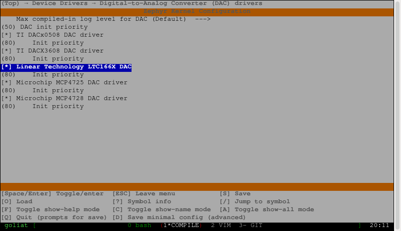
CONFIG_DAC_LTC166X_INIT_PRIORITY, \
<c166x_driver_api)
/*
* LTC1660: 10-bit
*/
#define LTC1660_DEVICE(n) LTC166X_DEVICE(1660, n, 10, 8)
/*
* LTC1665: 8-bit
*/
#define LTC1665_DEVICE(n) LTC166X_DEVICE(1665, n, 8, 8)
#define CALL_WITH_ARG(arg, expr) expr(arg)
#define INST_DT_LTC166X_FOREACH(t, inst_expr) \
LISTIFY(DT_NUM_INST_STATUS_OKAY(lltc_ltc##t), \
CALL_WITH_ARG, (), inst_expr)
INST_DT_LTC166X_FOREACH(1660, LTC1660_DEVICE);
INST_DT_LTC166X_FOREACH(1665, LTC1665_DEVICE);
Most of the driver part should be rather self-explained. The driver consists of only four functions:
- ltc166x_reg_write: write data to actual register.
- ltc166x_channel_setup: validate channel configuration provided by application.
- ltc166x_write_vale: validate data from application and then call ltc166x_reg_write.
- ltc66x_init: make sure that the SPI bus is ready. Used by DEVICE_DT_DEFINE.
The only tricky part is the macro-magic that is used for device registration:
#define INST_DT_LTC166X(inst, t) DT_INST(inst, lltc_ltc##t)
#define LTC166X_DEVICE(t, n, res, nchan) \
static const struct ltc166x_config ltc##t##_config_##n = { \
.bus = SPI_DT_SPEC_GET(INST_DT_LTC166X(n, t), \
SPI_OP_MODE_MASTER | \
SPI_WORD_SET(8), 0), \
.resolution = res, \
.nchannels = nchan, \
}; \
DEVICE_DT_DEFINE(INST_DT_LTC166X(n, t), \
<c166x_init, NULL, \
NULL, \
<c##t##_config_##n, POST_KERNEL, \
CONFIG_DAC_LTC166X_INIT_PRIORITY, \
<c166x_driver_api)
/*
* LTC1660: 10-bit
*/
#define LTC1660_DEVICE(n) LTC166X_DEVICE(1660, n, 10, 8)
/*
* LTC1665: 8-bit
*/
#define LTC1665_DEVICE(n) LTC166X_DEVICE(1665, n, 8, 8)
#define CALL_WITH_ARG(arg, expr) expr(arg)
#define INST_DT_LTC166X_FOREACH(t, inst_expr) \
LISTIFY(DT_NUM_INST_STATUS_OKAY(lltc_ltc##t), \
CALL_WITH_ARG, (), inst_expr)
INST_DT_LTC166X_FOREACH(1660, LTC1660_DEVICE);
INST_DT_LTC166X_FOREACH(1665, LTC1665_DEVICE);
Which became even more trickier as I wanted the driver to support both LTC1660 and LTC1665. To give some clarity, this is what happens:
- INST_DT_LTC166X_FOREACH expands for each node compatible with "lltc,ltc1660" or "lltc,ltc1665" in the devicetree.
- A struct ltc166x_config will be created for each instance and populated by the arguments provided by LTC1665_DEVICE or LTC1660_DEVICE.
- The ltc166x_driver_api struct is common for all instances.
- DEVICE_DT_DEFINE creates a device object and set it up for boot time initialization.
The documentation describe these macros more in depth.
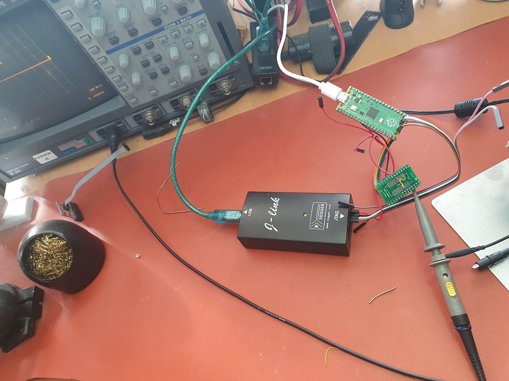
Test of the driver
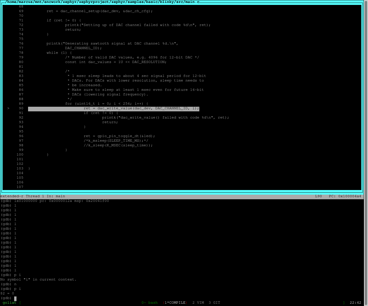
Zephyr has a lot of sample applicatons. I used samples/drivers/dac/src/main.c to test my driver
/*
 * Copyright (c) 2020 Libre Solar Technologies GmbH
 *
 * SPDX-License-Identifier: Apache-2.0
 */

#include <zephyr/kernel.h>
#include <zephyr/sys/printk.h>
#include <zephyr/drivers/dac.h>

#define ZEPHYR_USER_NODE DT_PATH(zephyr_user)

#if (DT_NODE_HAS_PROP(ZEPHYR_USER_NODE, dac) && \
        DT_NODE_HAS_PROP(ZEPHYR_USER_NODE, dac_channel_id) && \
        DT_NODE_HAS_PROP(ZEPHYR_USER_NODE, dac_resolution))
#define DAC_NODE DT_PHANDLE(ZEPHYR_USER_NODE, dac)
#define DAC_CHANNEL_ID DT_PROP(ZEPHYR_USER_NODE, dac_channel_id)
#define DAC_RESOLUTION DT_PROP(ZEPHYR_USER_NODE, dac_resolution)
#else
#error "Unsupported board: see README and check /zephyr,user node"
#define DAC_NODE DT_INVALID_NODE
#define DAC_CHANNEL_ID 0
#define DAC_RESOLUTION 0
#endif

static const struct device *const dac_dev = DEVICE_DT_GET(DAC_NODE);

static const struct dac_channel_cfg dac_ch_cfg = {
    .channel_id  = DAC_CHANNEL_ID,
    .resolution  = DAC_RESOLUTION
};

void main(void)
{
    if (!device_is_ready(dac_dev)) {
        printk("DAC device %s is not ready\n", dac_dev->name);
        return;
    }

    int ret = dac_channel_setup(dac_dev, &dac_ch_cfg);

    if (ret != 0) {
        printk("Setting up of DAC channel failed with code %d\n", ret);
        return;
    }

    printk("Generating sawtooth signal at DAC channel %d.\n",
        DAC_CHANNEL_ID);
    while (1) {
        /* Number of valid DAC values, e.g. 4096 for 12-bit DAC */
        const int dac_values = 1U << DAC_RESOLUTION;

        /*
         * 1 msec sleep leads to about 4 sec signal period for 12-bit
         * DACs. For DACs with lower resolution, sleep time needs to
         * be increased.
         * Make sure to sleep at least 1 msec even for future 16-bit
         * DACs (lowering signal frequency).
         */
        const int sleep_time = 4096 / dac_values > 0 ?
            4096 / dac_values : 1;

        for (int i = 0; i < dac_values; i++) {
            ret = dac_write_value(dac_dev, DAC_CHANNEL_ID, i);
            if (ret != 0) {
                printk("dac_write_value() failed with code %d\n", ret);
                return;
            }
            k_sleep(K_MSEC(sleep_time));
        }
    }
}
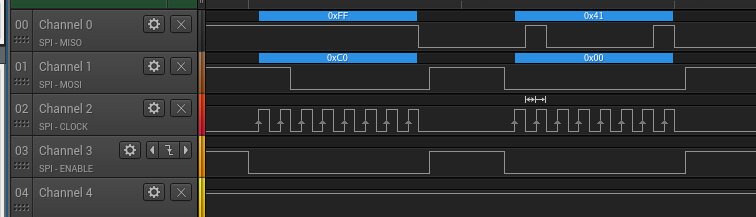
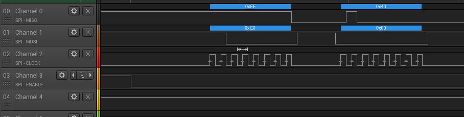
The application generates a saw-tooth signal on DAC_CHANNEL_ID. Here is the result:

Looks great!